Hello.
I want to change in KMotionCNC the way that in the Gcode
viewer screen the part for cutting is shown.
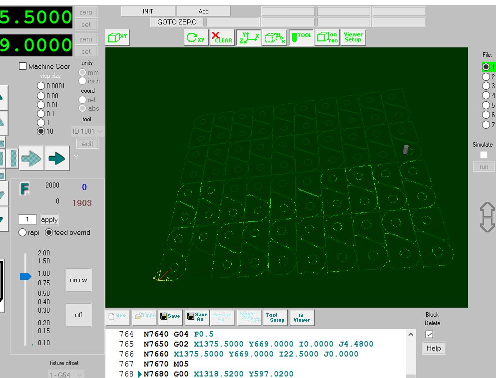
Now you press the "simulate" button and the part is drawn
at the screen with green color and the rapid movements
with red. After the green "Start" button is pressed the
drawed part is erased and starts to drawed again in real
time the actual path the tool is doing.
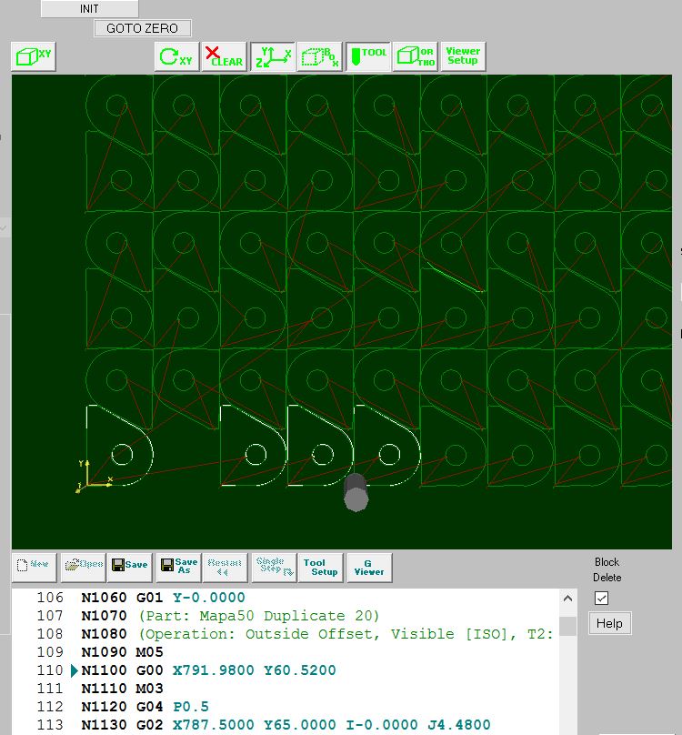
I want to change it in the way, that when you press the
"Start" button the part should not be erased and the
actual cutted path be shown with different color like
white, on the drawed part.
I was able to make some changes in the KMotionCNC program,
by manipulating the command
"m_ColorFeed.Set(0,255,0,128);"
The problem is that the color is changing, but it is not
shown on the screen. The time the tool is passing on the
previous drawed path with white color it is still shown
green. I also try with different values at alpha parameter
in the ColorFeed.Set() function but it seems not to be
changing anything.It suppose to change the transparency of
the color. Can anyone suggest another approach to the
issue?
Regards.